Control System |
Initially, the power and control system was a DC cab system with a hardwired control panel. There are some pictures of it in the layout construction album. After spending several months constructing and debugging this system, right of way negotiations resulted in an expansion of the layout area and a major line change. The hardwired control panel was suddenly junk as it could not be modified for the new track plan. So out it went. I did manage to salvage the switches, and LEDs. They're in a box somewhere in the shop. Then the present Windows based system was started. At first it was still a DC cab system, but eventually it was converted to DCC.
The power and control computer program evolved to become an integrated system using Digitrax DCC to control the locomotives and CMRI/SMINI boards (from JLC Enterprises) to control turnouts and signals. I wrote the program for Windows in Microsoft Visual C++. This software based system can accommodate changes in the track plan, some of which are already being considered. The host PC (operating under Windows XP) drives four flat panel monitors distributed around the layout. An identical image is displayed on each monitor using a four channel video distribution amplifier. Each control station also has a USB mouse. There is only one keyboard and it is located at the main command station.
Most, if not all of the functionality of the Visual C++ control program could have been achieved using JMRI Panel Pro This would be the way to go if you are not already proficient in a programming language like Visual C++.
Since I usually operate the layout by myself or with just one or two friends, the control system is intended to be used by a single person walking around the layout with a wireless throttle (or using an on-screen throttle). If there is more than one operator, to prevent chaos, generally only one person is allowed to use the command stations. Any command function can be executed from any command station. Thus complete control of the entire layout is possible from any of the four command stations. Turnouts are toggled between normal and thrown by clicking on them or by using push buttons located on the fascia.The PC communicates with the CMRI/SMINI boards using a serial RS-232 port. The RS-232 signal is converted to RS-485 which then goes to each SMINI board. The PC polls each SMINI board in turn and waits for its response. When the last of the five SMINIs has responded with its current input states, a new set of output states for all of the devices controlled by SMINI is computed and sent to each board. Then the SMINI polling is started again to continue the I/O loop. The serial communication is done using overlapped I/O in a secondary thread, so that the command program is free to do other processing while waiting for the SMINI boards to respond.
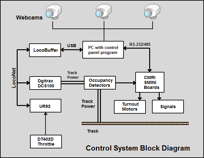
The SMINI inputs are fascia push buttons located near turnouts, buttons to close the lift bridge, track occupancy detectors, and open bridge micro switches (for bridge status display and block power interlocking). The SMINI outputs control Tortoise switch motors, signals, block power relays, and the lift bridge electro-magnet relay. The following illustration diagrams the information flow between these various components. Some detail has been omitted for clarity.
The PC communicates with the Digitrax DCS100 command station using a LocoBuffer-USB interface. LocoNet communication is also done with a secondary thread that monitors the LocoNet. When a LocoNet packet is received, the program looks at it, and decides whether or not there is anything of interest in it. Examples of pertinent Loconet packets are throttle commands that can be used to interpret and display train speed in miles per hour (the program data base includes a speed table for each locomotive), wireless throttle turnout commands, a wireless throttle command to close the lift bridge, and commands to set turnouts for pre-defined routes.
The command program can also send commands to locomotives when the user has invoked an on-screen throttle and it can edit universal consists. The edit consists dialog also displays the status of all occupied slots in the Digitrax DCS100 command station and can free any slots. This greatly facilitates slot management and avoids running out of slots because too many of them are occupied with garbage.
A screen capture from the command program is shown below (click to enlarge, use your browser back button to come back).
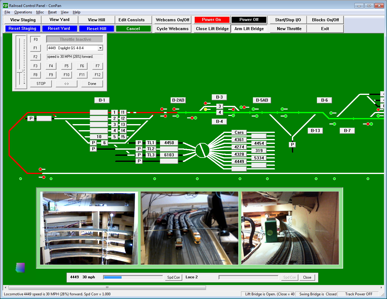
Referring to the above screen capture, you will notice that occupied track blocks are shown in red with a projected route and direction shown in green. Each time a turnout position is changed or block occupancy changes, the route projections are recomputed. The helps the operator avoid unintended train destinations, especially when talking to visitors and operating a train at the same time.
The signal aspects are also shown on the control program screen. The signals are currently programmed as a simple ABS system using red, yellow, and green aspects. An "approach lighting" feature can be turned on or off. I generally run the layout with all signals lit.
While there is some code in the control program that is specific to this layout, the program is largely table driven. That is, the track diagram, block definitions, CMRI card and pin numbers for turnouts, occupancy detectors, on-screen buttons, and signal definitions, are all contained in a layout definition file that is external to the program. Most layout configuration changes can be made by editing the layout definition file rather than the program source code. The layout definition file also has a locomotive roster that contains locomotive numbers, descriptive data, and scale speed vs. throttle setting tables. This information is useful in drop down lists for locomotive selection and for display of locomotive speed in scale miles per hour.
Web Cams
The helix, upper level reverse loop, and helper Y are all hidden inside the large mountain at the end of the peninsula. Web cams are used to provide a view of these tracks. The web cam windows are displayed across the bottom of the control panel program. From left to right, the first view shows the interior of the helix. At the top of the image, the turnout and end of the helper reversing Y is visible. Just below that, you can see one side of the upper level reversing loop. The lower half of the image shows the double track helix. The second view shows the staging yard throat. The lower level reversing loop can be seen in the distance. While this area is visible from an aisle, it is frequently convenient to see what's going on there from the other side of the peninsula. The last view shows the tracks at the top of the helix. The leftmost turnout leads to the top of the double tracked helix. The track on the right is one end of the upper level reversing loop. There are a total of five web cams. The "Cycle Webcams" button can be used to cycle through them. The additional views are of the staging yard and staging yard throat.
As shown in the following figure, hovering the mouse cursor over any of the three video windows will zoom that window. The window returns to normal size when the cursor leaves the window.
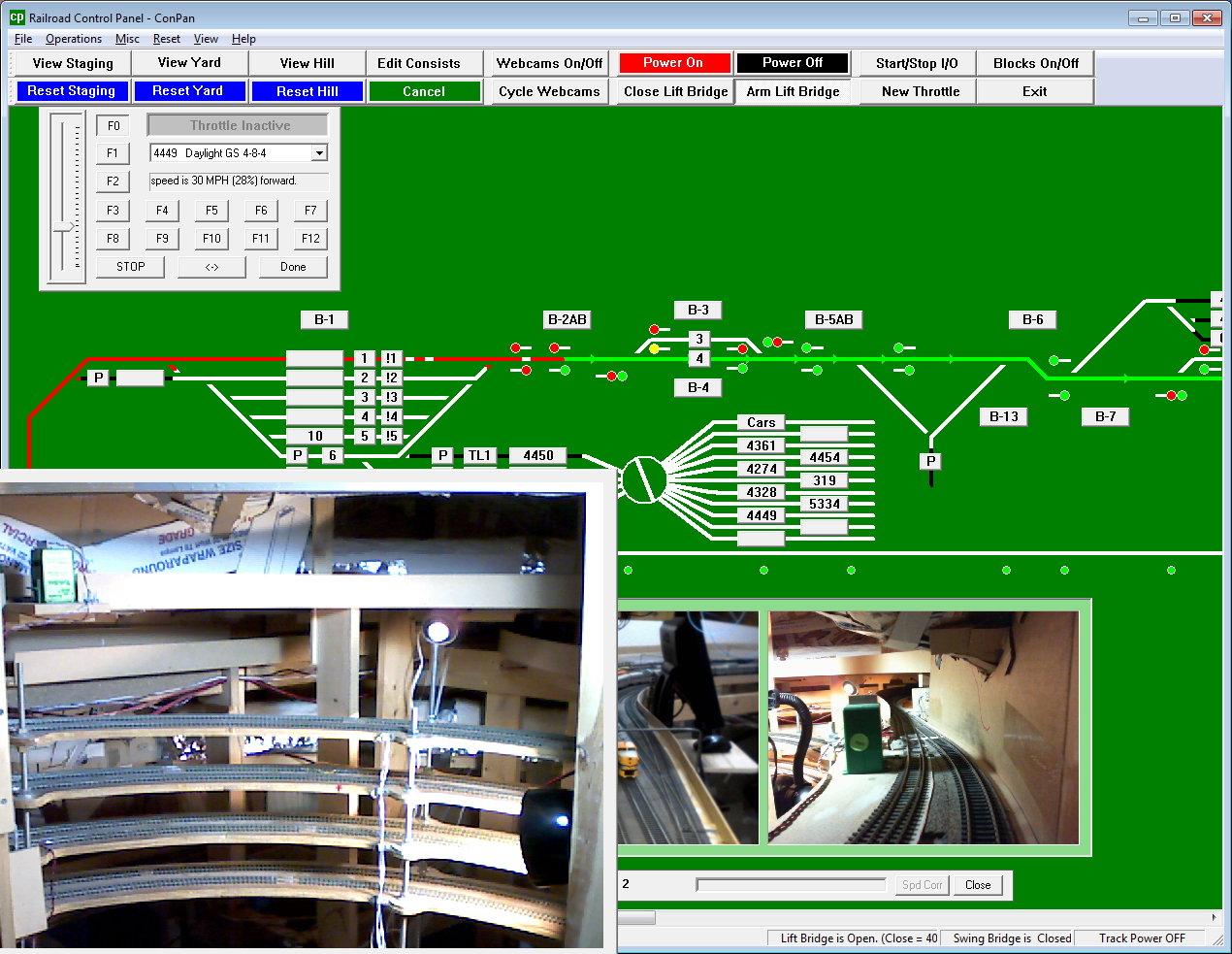
Incorporation of the webcam views in the control panel program is done using the "VideoInput" library developed by Theodore Watson. Many thanks to Mr. Watson for creating and making this software library available. Without it, adding the webcams to the control panel program would have been a daunting task indeed.
Programming Locomotive Decoders
All locomotive decoder programming is done with JMRI Decoder Pro as this system is a free download, works well, and would be hard for me to improve on. When I'm using Decoder Pro, the main control program must be shut down as Decoder Pro uses the same hardware to access the LocoNet. In that case I use small a Panel Pro application to control the lower yard power and turnouts while programming locomotives.